














JVM1533WD - Instructions
Keep searches simple. Use keywords, e.g. "leaking", "pump", "broken" or "fit".
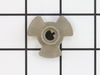
Turntable Coupler had been broken off, by previous owner.
I just matched the prong in the turntable hole and coupler fit into the hole perfectly. All The Best.
Parts Used:
-
Donna from WEST PALM BCH, FL
-
Difficulty Level:Really Easy
-
Total Repair Time:Less than 15 mins
4 of 5 people
found this instruction helpful.
Was this instruction helpful to you?
Thank you for voting!
The microwave had been mistakenly turned on with nothing in it and the turntable coupler was badly burned. Pieces of it eventually broke off.
The burned remnant of the coupler was a bit difficult to remove. I did so with a pliers and also used the pliers to clear out some burned fragments of the coupler. With a flashlight I determined that the slot for the coupler was now clear. I matched the configuration of the slot with that of the new coupler and it slid immediately into place with no difficulty whatever.
Parts Used:
-
Peter from FREDERICKSBRG, VA
-
Difficulty Level:A Bit Difficult
-
Total Repair Time:Less than 15 mins
-
Tools:Pliers
3 of 3 people
found this instruction helpful.
Was this instruction helpful to you?
Thank you for voting!
When the MW door was opened a fan would start running. Close the door the fan would go off.
Removed the MW from the wall. Took the top screws off the air vent. Then removed the two screws holding on the display. I then moved the display to its side and it revealed the micro switches. I removed the plug in leads from the micro switch one at a time. I did this with all three micro switches only one at a time. I reinstalled everything and plugged it in. No more fans starting when the door is opened.
Parts Used:


-
vic from Allen, TX
-
Difficulty Level:Easy
-
Total Repair Time:15 - 30 mins
-
Tools:Screw drivers
4 of 6 people
found this instruction helpful.
Was this instruction helpful to you?
Thank you for voting!
Door switch was burnt out
-
Edward from ORCHARD PARK, NY
-
Difficulty Level:Really Easy
-
Total Repair Time:15 - 30 mins
-
Tools:Nutdriver
5 of 10 people
found this instruction helpful.
Was this instruction helpful to you?
Thank you for voting!
UNABLE TO INSTALL DUE TO DAMAGED IN SHIPPING
WORTHLESS...I EMAILED YOU ON 2/7/22 AFTER RECEIVING THE DAMAGED FILTER DUE TO NOT SHIPPING IN A HARD OR SOMETHING IN THE ENVELOPE TO PROTECT THE FILTER FROM BEING BENT.
I HAVE NOT HAD ANY RESPONSE FROM YOU FOR THE DAMAGED FILTER OR WHEN I CAN EXPECT ONE THAT I CAN USE.
UNSATISIFACTORY SERVICE!
I HAVE NOT HAD ANY RESPONSE FROM YOU FOR THE DAMAGED FILTER OR WHEN I CAN EXPECT ONE THAT I CAN USE.
UNSATISIFACTORY SERVICE!
Parts Used:

-
Tina from EL DORADO, KS
-
Difficulty Level:Very Difficult
-
Total Repair Time:More than 2 hours
3 of 4 people
found this instruction helpful.
Was this instruction helpful to you?
Thank you for voting!
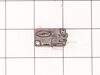
the turn table no turn and no heat the food. but the bottom oven worked
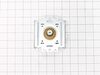
well I unplugged the microwave one day prior to working on it. shock precaution smart way to do this job. very easy pullout the screws behind the unit pull off the outer casing. minor screws inside the unit you have to remove a couple things out of the way. unplug the magnetron and remove first gives you more room to work on the side panel to replace the micro switches. I only replaced one the bottom micro switch. only one bad, but since I was in there I clean the bulb and changed the magnetron any ways. I read other reviews and made my choice to do so. it works perfectly now. Thanks PartSelect for having parts.
Parts Used:
-
mark from SANBORN, NY
-
Difficulty Level:Really Easy
-
Total Repair Time:15 - 30 mins
-
Tools:Screw drivers
3 of 4 people
found this instruction helpful.
Was this instruction helpful to you?
Thank you for voting!
Would not heat and made a buzzing or popping sound
Unplug the microwave. Remove the Philips head and safety Torx head screws along the bottom of the sides and rear of the microwave which hold the black cover on. Lift the cover up at the rear and slide it backwards to disengage the tabs on the front top. Remove the cover. Discharge the capacitor by shorting the terminals to each other and then ground. Do this with a well insulated object and be aware there may be a pop when you do this. Keep hands, etc. on the insulated part of the object (screwdriver handle, etc). There's a lot of stored energy in that capacitor. I'd advise first checking the diode to make sure its not bad. Replace it if it is. The Magnatron is held in with a couple of screws on the top and sides. Unplug the connector and remove the screws. Remove the Magnatron. Installation is the reverse of removal.
Parts Used:
-
Thomas from NEWARK, DE
-
Difficulty Level:Easy
-
Total Repair Time:15 - 30 mins
-
Tools:Screw drivers
4 of 7 people
found this instruction helpful.
Was this instruction helpful to you?
Thank you for voting!
Handle broke where screws come thru door.
turning two old screws out holding broken piece with needle nose plyers while turnning the philips screw is straight forward BUT getting at the screws is somewhat difficult. The black frame on the inside of the door over the screws must be pried out of the door to allow access to the screw heads. This black frame is held in place by compression and there is no place to begin prying it out other than with a very thin object like a kitchen spatula or very thin putty knife, only pry out 20% over the screws.It would be nice if extra screws were included with the handle as YOU WILL DROP at least one.
Parts Used:

-
Paul from Thousand Oaks, CA
-
Difficulty Level:A Bit Difficult
-
Total Repair Time:15 - 30 mins
-
Tools:Pliers, Screw drivers
3 of 4 people
found this instruction helpful.
Was this instruction helpful to you?
Thank you for voting!
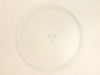
Glass tray somehow got a nick in the edge, a few days later it split while in use.
Another company said the new plate would arrive in mid-March, this company seemed to be faster so ordered the tray here, and it came in less than a week. I put the turn button back in the center hole, set the wheeled ring on the bottom of the oven, fitted the new glass tray onto the turn button.
Parts Used:
-
Delores from Portland, OR
-
Difficulty Level:Very Easy
-
Total Repair Time:Less than 15 mins
3 of 4 people
found this instruction helpful.
Was this instruction helpful to you?
Thank you for voting!
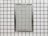
Too dirty to clean, bought new parts.
I had already removed the old grease filters. Unwrapped the new grease filters and popped into place. No tools were necessary.
Parts Used:
-
Debora from Saugus, MA
-
Difficulty Level:Really Easy
-
Total Repair Time:Less than 15 mins
3 of 4 people
found this instruction helpful.
Was this instruction helpful to you?
Thank you for voting!
Oven would not start when closing door.
Removed some cosmetic panels. Removed the assembly with micro switches. Examined the faulty switch by checking the clicking action of switch. Two others were ok by this method. Replaced the switch with new one. Works fine so far. Thanks to web site and YouTube videos.
Parts Used:
-
Raymond from DEPEW, NY
-
Difficulty Level:Easy
-
Total Repair Time:Less than 15 mins
-
Tools:Screw drivers
4 of 8 people
found this instruction helpful.
Was this instruction helpful to you?
Thank you for voting!
Items were not getting heated up in the microwave,
I went to LG website enter model number and was given a list of parts that need to be replaced with a percentage of which part fails the most. I order micro switch PS3522738 which arrived and PS3529293 was backordered. I installed the one that arrived. The microwave worked briefly. I reordered and waited for both switches to arrive and installed both. The microwave still doesn't work.
Parts Used:
-
Kenneth from CRYSTAL LAKE, IL
-
Difficulty Level:Really Easy
-
Total Repair Time:15 - 30 mins
-
Tools:Screw drivers
2 of 2 people
found this instruction helpful.
Was this instruction helpful to you?
Thank you for voting!
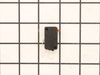
Microwave not turning on. All other functions operate
DISCONNECT THE POWER CORD and discharge the capacitor
Leave unplugged overnight
Remove vent grille by removing the 2 philips screws
Remove the LED panel by removing 1 phillips screw
Disconnect all connectors that plug into back of the LED board completely
Remove the wires from the switches (3) at the inside edge of the microwave door
Gently remove each switch housing and test all three switches for continuity
Carefully replace non-functioning switches and reassemble the panel
GOOD LUCK
Leave unplugged overnight
Remove vent grille by removing the 2 philips screws
Remove the LED panel by removing 1 phillips screw
Disconnect all connectors that plug into back of the LED board completely
Remove the wires from the switches (3) at the inside edge of the microwave door
Gently remove each switch housing and test all three switches for continuity
Carefully replace non-functioning switches and reassemble the panel
GOOD LUCK
Parts Used:
-
Tom from DENVER, CO
-
Difficulty Level:A Bit Difficult
-
Total Repair Time:1- 2 hours
-
Tools:Screw drivers
2 of 2 people
found this instruction helpful.
Was this instruction helpful to you?
Thank you for voting!
The power was on but the Microwave would not start.
This is an above the range microwave, use 2 people to remove it. I set it on a table and removed the outer cabinet. I then used jumper leads to discharge the capacitor. I removed the control panel (taking a picture to ensure proper wiring on assembly), then I removed the latch board. Once I had the latch board out I removed the monitor switch (which is the middle switch) and tested it for continuity. This is a normally closed switch. I tested the other two switches as well and found these (normally open) switches for continuity to be good and the monitor switch to have a short. This switch should show continuity when the door is open and should show no resistance when the door is closed. (Take care removing the switches) After I received the parts I installed them in the new Locker Holder and installed the latch board (ensure to follow the latch board adjustment steps located in the control board). I then attached the wiring to the control board and then plugged in the unit. I tested the unit to ensure it functioned correctly. I then installed the outer cabinet, and then installed the unit above the range (Use 2 people for this process). Overall an easy fix you just need to ensure you follow safety procedures (especially when dealing with capacitors.
Take a lot of pictures of the wiring and of the components and take care with the latch board or you'll have to buy a new one when all you really needed is a monitor switch.
Take a lot of pictures of the wiring and of the components and take care with the latch board or you'll have to buy a new one when all you really needed is a monitor switch.
Parts Used:


-
William from KINGMAN, AZ
-
Difficulty Level:A Bit Difficult
-
Total Repair Time:1- 2 hours
-
Tools:Nutdriver, Pliers, Screw drivers
3 of 5 people
found this instruction helpful.
Was this instruction helpful to you?
Thank you for voting!
Frost build up on bottom to ice bin and delivery chute in door creating ice blockage
Remove the ice bin.
Turn the ice maker selection to "OFF"
Use small flat blade screwdriver to open the plastic ears on the electic plug in connectiion
Use #2 Phillips screwdriver to remove the screw on the front left side of the ice maker
Pull the ice maker forward until free of the two studs in the left side rear of the freezer wall
Check to see if the supplied water chute is the correct size for your application, if not remove the water chute from the old ice maker and place it on the new one.
Place the new ice maker in the freezer connecting the slots on the left read with the studs on the left wall
NOTE; IF THE ICE MAKER DOES NOT APPEAR TO BE LEVEL HORIZONTALLY REMOVE IT AND CAREFULLY REINSTALL IT TO ACHIEVE LEVEL
NOTE: ENSURE THE WATER DELIVERY TUBE RESTS IN THE RECEIVER TRAY
Reconnect the electrical plug ( needle nose pliers may be helpful in aligning the male plug with the female plug)
Move the selector from "OFF" to "ON"
Replace the ice bin and close the freezer door
Turn the ice maker selection to "OFF"
Use small flat blade screwdriver to open the plastic ears on the electic plug in connectiion
Use #2 Phillips screwdriver to remove the screw on the front left side of the ice maker
Pull the ice maker forward until free of the two studs in the left side rear of the freezer wall
Check to see if the supplied water chute is the correct size for your application, if not remove the water chute from the old ice maker and place it on the new one.
Place the new ice maker in the freezer connecting the slots on the left read with the studs on the left wall
NOTE; IF THE ICE MAKER DOES NOT APPEAR TO BE LEVEL HORIZONTALLY REMOVE IT AND CAREFULLY REINSTALL IT TO ACHIEVE LEVEL
NOTE: ENSURE THE WATER DELIVERY TUBE RESTS IN THE RECEIVER TRAY
Reconnect the electrical plug ( needle nose pliers may be helpful in aligning the male plug with the female plug)
Move the selector from "OFF" to "ON"
Replace the ice bin and close the freezer door
Parts Used:

-
Ronald from PONCA CITY, OK
-
Difficulty Level:Really Easy
-
Total Repair Time:15 - 30 mins
-
Tools:Pliers, Screw drivers
3 of 5 people
found this instruction helpful.
Was this instruction helpful to you?
Thank you for voting!